
- All
- Product Name
- Product Keyword
- Product Model
- Product Summary
- Product Description
- Multi Field Search
Email: sales@njrecgroup.com
Views: 0 Author: Site Editor Publish Time: 2026-09-02 Origin: Site
Selecting the correct mechanical load rating for power lines requires a delicate balancing act. You must ensure maximum transmission line safety while keeping project budgets strictly under control. Every single component on a high-voltage grid plays a critical role in system stability.
The engineering term "70 kN" refers directly to the Specified Mechanical Load (SML). It represents the absolute maximum tension the unit can safely withstand before experiencing structural failure. Engineers rely heavily on this precise metric. It guarantees the heavy overhead conductors remain securely aloft during extreme weather events.
Specifying a 70 kN unit requires a deep understanding of line tension calculations. You must also evaluate tower configurations and international compliance standards carefully. Mastering these concepts helps you avoid catastrophic grid failures. Reading this guide will also help you eliminate unnecessary procurement costs.
70 kN defines the breaking load: It equals 70 kilonewtons (approximately 15,736 lbf) of mechanical tension capacity.
Ideal for specific applications: Predominantly used on suspension (straight-line) towers in medium-to-high voltage transmission and distribution lines, rather than heavy-duty dead-end towers.
U70BS is the industry standard: The "U70BS" designation specifies a standard type glass insulator with ball-and-socket fittings rated for 70 kN.
Visual fail-safe: Toughened glass at this load rating cannot be hidden-punctured; if the mechanical or electrical limit is exceeded, the glass shell shatters completely while the metal pin holds the line securely.
The Specified Mechanical Load (SML) serves as a verified structural breaking point. Manufacturers guarantee this exact baseline limit under strict global testing frameworks. These frameworks include rigorous standards like IEC 60383 and ANSI C29.2. Testing facilities physically pull the units apart to verify this rating. The hardware must withstand intense physical stress before snapping. The 70 kN rating proves the unit possesses immense mechanical endurance.
We must differentiate SML from the Routine Test Load (RTL). The SML dictates the ultimate breaking limit. Conversely, the RTL represents a continuous proof load. Testing facilities apply the RTL to every single unit before shipping. The RTL typically equals 50% of the SML. Therefore, a 70 kN unit experiences an exact 35 kN routine test load. This continuous factory testing ensures zero hidden manufacturing defects exist inside the shell.
You will frequently see the "U70BS" nomenclature printed on engineering schematics. We can break down this industry-standard code easily. The "U" universally stands for Insulator. The "70" clearly indicates the 70 kN SML rating. The "B" signifies a Ball and Socket coupling mechanism. Finally, the "S" identifies a Standard profile shape. This standardized naming convention eliminates dangerous procurement errors across global regions.
When you purchase a standard type glass insulator, engineers have designed it perfectly. They engineer these units to meet specific baseline mechanical parameters. These stringent parameters guarantee reliable grid performance. You can trust these units in highly predictable weather environments.
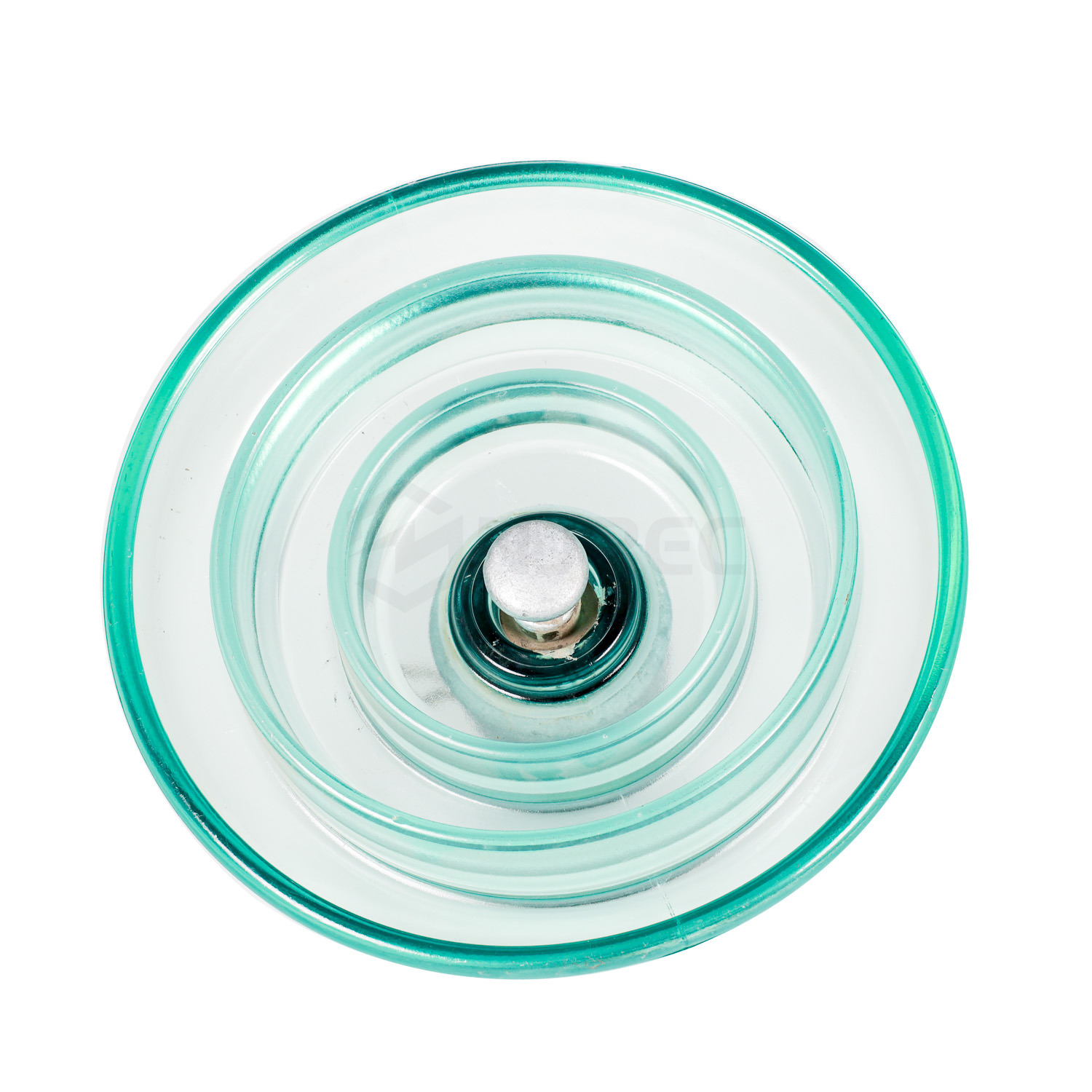
Grid planners deploy 70 kN hardware strings across highly specific voltage ranges. You will typically see them utilized in 11kV to 132kV networks. They serve as the reliable backbone for standard distribution operations. They also support medium-to-high voltage transmission lines effectively. Engineers trust this capacity for thousands of miles of rural and urban infrastructure.
Understanding tower placement logic remains critical for grid reliability. Engineers must choose between suspension towers and tension towers carefully. Suspension towers operate in straight lines across flat terrain. These straight-line towers primarily support the downward vertical weight of the conductor. They also resist normal transverse wind loads pushing horizontally against the cables. A 70 kN capacity proves usually sufficient for these straight-line suspension roles. The downward gravitational forces rarely exceed these safe working limits.
Tension towers serve a completely different architectural purpose on the grid. We often call them dead-end towers or angle towers. These specific locations bear the full horizontal pulling tension of the entire cable. They act as heavy-duty anchor points for the transmission line. Because of this massive horizontal strain, engineers must step up the mechanical ratings significantly. These anchor zones often require robust 120 kN or 160 kN units. Installing a 70 kN string here would invite immediate disaster.
Stringing a disc suspension glass insulator at the correct tower location optimizes longevity. It ensures the hardware capacity matches the physical environmental demands perfectly. Correct placement prevents premature mechanical fatigue and system failures.
You need a solid, evidence-based framework for calculating required SML values. Engineers evaluate the exact span length between towers first. Longer spans create heavier cable weights. They calculate the total conductor weight across that specific span. Next, they factor in the maximum historical wind velocities for the region. Finally, they account for potential heavy ice loading in freezing climates. All these dynamic forces combine to dictate the required mechanical strength.
Placing a 70 kN unit in a 120 kN zone creates massive hazards. This error represents severe under-specifying. River crossings and heavy ice zones demand much higher tension ratings. If wind or ice pushes the physical load past 70 kN, catastrophic grid failures occur. The high-voltage line will drop to the ground. This drop causes dangerous regional outages and sparks potential wildfires.
Conversely, over-specifying creates entirely different problems for project managers. Indiscriminately ordering 120 kN or 160 kN hardware causes massive budget bloat. Heavier units cost significantly more to manufacture, transport, and install. You waste valuable project funds by over-engineering simple straight-line spans. A 70 kN toughened glass insulator meets all safety margins perfectly here. It handles standard suspension roles without draining your financial resources.
Grid engineers never run hardware at its maximum physical capacity. They introduce a standard safety factor to choose the correct SML. This mathematical safety factor usually ranges from 2.5 to 3.0. If your calculated maximum line tension hits 25 kN, you multiply it by 2.8. The mathematical result equals exactly 70 kN. This standard formula ensures a massive strength buffer against unexpected weather events.
Table 1: Mechanical Load Application Framework
Tower Type & Location | Primary Load Direction | Recommended Minimum SML | Engineering Justification |
|---|---|---|---|
Standard Suspension (Straight-Line) | Vertical (Downward Weight) | 70 kN | Easily supports conductor weight and moderate wind in 11kV-132kV lines. |
Light Angle Suspension | Vertical + Slight Transverse | 70 kN - 100 kN | Requires slight capacity increase to handle minor horizontal turning forces. |
Heavy Tension / Dead-End | Horizontal (Pulling Strain) | 120 kN - 160 kN | Bears the full pulling tension of the entire conductor span. |
Major River or Highway Crossing | Horizontal + Extreme Wind | 160 kN - 210 kN+ | Long spans create massive cable weight and amplified wind oscillation risks. |
High-quality raw materials possess an inherently high dielectric strength. Electrical surges will naturally flash over the exterior surface of the shell. They will not puncture the solid interior body. This powerful puncture resistance makes a glass insulator highly dependable during severe lightning strikes. The physical tempering process creates compressive stress layers on the surface. These layers fight off both mechanical impacts and electrical degradation simultaneously.
We must discuss the unique "fail-safe" shattering characteristic. If physical forces accidentally breach the 70 kN mechanical limit, a fascinating reaction occurs. The shell spontaneously shatters into harmless, small granules. It completely disintegrates in a fraction of a second. However, the internal metal cap and pin remain perfectly intact. This brilliant design securely holds the line. It actively prevents the heavy conductor from dropping onto the terrain below.
When evaluating dimensional parameters, you must consider the aerodynamic profiles carefully. You must choose between standard profiles and anti-fog profiles. Both designs exist within the 70 kN load class.
Standard Profiles: These feature smooth under-ribs. They work exceptionally well in clean, unpolluted rural environments.
Anti-Fog Profiles: These feature much deeper, aerodynamic outer ribs. They dramatically increase the total creepage distance.
Open Profiles: These feature an open aerodynamic design. They allow heavy rain to wash away severe industrial pollution naturally.
These dimensional variations prevent dangerous electrical arcing. You must select the right profile for heavily polluted coastal or industrial zones.
Maintenance teams gain a massive operational advantage through visual inspections. Inspectors can easily spot a shattered 70 kN disc from a moving helicopter. They can also use automated drones to scan the lines rapidly. The missing transparent shell becomes instantly visible from the air. This visibility completely eliminates the need for expensive instrument testing. Older porcelain or modern composite units require slow, manual instrument testing to find hidden internal faults.
Proper transportation and installation remain vital for system longevity. Mishandling hardware introduces severe hidden risks before the power even turns on. You must follow strict handling guidelines to protect the 70 kN capacity.
Keep all units securely packed in their original wooden crates until reaching the final installation site.
Avoid striking the edges of the transparent shells against any steel tower members during lifting operations.
Never drop the units onto hard ground. This harsh impact causes microscopic internal stress fractures.
Inspect each unit visually for pre-installation micro-fractures before hoisting them up to the crossarms.
Preventing these micro-fractures in the shell ensures maximum reliability. The hardware will perform perfectly if you handle it with professional care.
The empirical lifecycle expectations of high-quality units remain incredibly impressive. They often span 40 to 50 years in active service. They degrade incredibly slowly in standard outdoor weather conditions. The tempered shells ignore heavy UV radiation entirely. They easily reach this half-century mark provided you meet one crucial condition. Your daily routine mechanical loads must never exceed the 35 kN RTL threshold. Maintaining this physical load boundary guarantees decades of highly stable performance.
The 70 kN rating represents a highly specific, mathematically justified mechanical threshold. It serves as the absolute ideal load capacity for standard suspension applications. Engineers across global power grids rely on this specification for medium-to-high voltage lines.
Procurement and engineering teams must verify manufacturing quality rigorously. We strongly advise you to demand certified Type Test Reports from all potential suppliers. Look specifically for independent mechanical failing load tests before shortlisting any factory.
Choosing the right standard type hardware impacts your project success immediately. It reduces your upfront CapEx substantially by eliminating unnecessary over-engineering. It also lowers your long-term OpEx through highly reliable performance and rapid, low-cost visual inspections.
A: Generally no, unless you operate a very light distribution line. Dead-end towers bear the absolute full horizontal tension of the cables. They typically require 120 kN or higher ratings to handle this intense pulling force safely. Using 70 kN here risks a catastrophic mechanical failure.
A: The suffix letters define the specific aerodynamic profile shape. The "S" in U70BS typically denotes the standard profile shape. Other letters indicate anti-fog or outer-rib designs meant for polluted areas. However, both units share the exact same 70 kN mechanical rating and ball-and-socket fitting.
A: The direct mathematical conversion shows that 70 kN equals roughly 7,138 kilograms or 15,736 pounds of static breaking force. This represents the ultimate breaking limit. However, engineers apply strict safety factors. The safe continuous working loads remain significantly lower, typically around 35 kN.


