
- All
- Product Name
- Product Keyword
- Product Model
- Product Summary
- Product Description
- Multi Field Search
Email: sales@njrecgroup.com
Views: 0 Author: Site Editor Publish Time: 2026-09-13 Origin: Site
Insulation coordination defines the ultimate reliability of 132 kV transmission networks. Under-specifying your string configurations directly leads to dangerous electrical flashovers and frequent grid outages. Conversely, over-specifying these assemblies inflates tower loads and drives up project budgets unnecessarily. Determining the exact string assembly presents a major engineering challenge for utility operators. Project teams must carefully balance theoretical phase voltage equations against severe real-world environmental stress and dynamic mechanical variables. This guide outlines the standard calculation framework for optimal string sizing in high-voltage grids. We will cover necessary environmental adjustments, physical implementation limits, and strict technical evaluation criteria. By following these evidence-based steps, you will confidently select the correct insulation components. This ensures your infrastructure achieves both operational safety and long-term mechanical stability.
Standard Count: A typical 132 kV transmission line requires 9 to 10 discs per suspension string under normal environmental conditions.
The Formula: (Line Voltage / √3) / Disc Voltage Rating + Safety Margin (usually 1–2 extra discs).
Material Advantage: A disc suspension glass insulator offers visual fault identification (it shatters rather than cracking invisibly), reducing maintenance inspection overhead.
Specification Driver: Final disc count and profile selection dictate compliance with IEC standards for creepage and electro-mechanical failing loads.
Establishing the theoretical minimum requirement is the first step before applying regional safety margins. This baseline prevents over-purchasing and keeps infrastructure designs mathematically grounded. We must evaluate the voltage breakdown precisely to understand how many units will safely isolate the live conductor from the grounded transmission tower.
Utility professionals often discuss 132 kV as a broad metric, but we must differentiate between system voltage and phase voltage. The 132 kV rating represents the line-to-line system voltage. However, the suspension string physically insulates the conductor from the grounded tower structure. Therefore, the actual stress placed on the string is the line-to-ground voltage, known as the phase voltage.
We calculate this phase voltage using a fundamental electrical engineering formula:
Determine Phase Voltage: Divide the line-to-line voltage (132 kV) by the square root of 3 (√3). This yields an actual phase voltage of approximately 76.2 kV.
Identify Per-Disc Capacity: A standard type glass insulator typically carries a safe working voltage rating of about 11 kV per unit under normal conditions.
Execute the Division: Divide the calculated phase voltage (76.2 kV) by the individual working voltage (11 kV). The mathematical result is 6.92.
Establish the Theoretical Minimum: Since you cannot install a fraction of a unit, you round this number up. This establishes an absolute theoretical baseline of 7 discs to handle the steady-state electrical stress.
However, running a power grid on theoretical minimums guarantees failure. Real-world transmission lines experience constant dynamic changes. You must apply a safety margin to this baseline. Engineers typically add 2 to 3 additional units to account for sudden system overvoltages and switching surges. Furthermore, this margin provides critical mechanical and electrical redundancy. If one unit unexpectedly shatters, the remaining string must continue to hold the line voltage safely until maintenance crews arrive. Adding this safety margin brings our final baseline to the industry standard of 9 to 10 discs.
The standard baseline calculation often fails when lines traverse extreme environments. You must evaluate the contextual surroundings of your transmission route to understand why standard counts fall short. Adjusting your procurement specifications based on environmental realities prevents catastrophic flashovers and minimizes unplanned maintenance outages.
Pollution represents the most common threat to dielectric stability. Heavy industrial pollution coats surfaces in conductive dust, while coastal regions subject lines to aggressive salt fog. Both conditions drastically reduce the effective insulation distance across the unit's surface. To counter this, engineers must increase the total creepage distance, usually measured in millimeters per kilovolt (mm/kV).
You can achieve this increased creepage in two ways. You can simply increase the total number of units, sometimes extending a 132 kV string to 11 or 12 discs. Alternatively, you can specify an anti-pollution profile. These specialized aerodynamic or double-shed designs maximize the surface tracking path without lengthening the overall physical string.
Altitude also dictates critical adjustments. When transmission lines exceed 1000 meters above sea level, the air density drops significantly. Thinner air provides weaker natural insulation around the hardware. This derating of air insulation lowers the overall impulse withstand voltage of the assembly. To compensate for reduced air density, engineers routinely add an extra disc to maintain the required safety thresholds.
Finally, regional lightning activity influences the final string design. In areas with high isokeraunic levels (frequent thunderstorm activity), strikes induce massive transient overvoltages. Extending the string improves the Basic Insulation Level (BIL), giving the grid a better chance to survive lightning-induced surges without flashing over.
Table: Environmental Factors and String Adjustments
Environmental Variable | Primary Technical Impact | Recommended Engineering Adjustment |
|---|---|---|
Industrial / Coastal Pollution | Conductive surface tracking reduces dielectric strength. | Add 1-2 discs or switch to anti-pollution aerodynamic profiles. |
High Altitude (>1000m) | Lower air density reduces impulse withstand voltage. | Add extra discs to compensate for air derating. |
High Isokeraunic Levels | Increased risk of lightning-induced overvoltages. | Extend string length to improve Basic Insulation Level (BIL). |
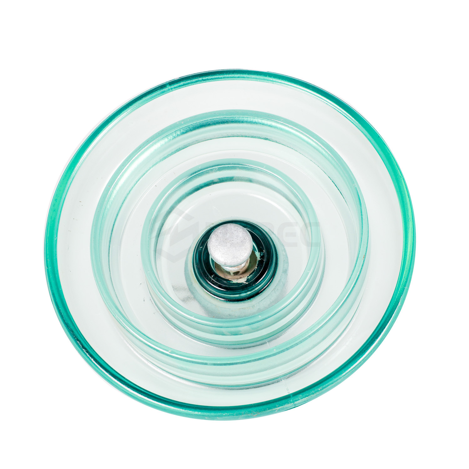
Knowing how many units to purchase is only half the battle. You must bridge the gap between quantity and technical quality. Selecting the exact specifications for your project dictates how well the grid performs under physical and electrical stress. You must evaluate specific solution categories and connect hardware features directly to operational outcomes.
Electro-Mechanical Strength, or Specified Mechanical Load (SML), serves as the foundational metric. For a 132 kV line, tensile load requirements typically fall into standardized brackets: 70kN, 100kN, 120kN, or 160kN. You cannot guess this number. You must match the mechanical rating to rigorous engineering calculations. These calculations factor in the exact weight of the bundled conductors, the span length between towers, and regional data for maximum wind and ice loading. Specifying a disc suspension glass insulator with adequate SML prevents catastrophic line drops during severe weather events.
Dielectric performance represents the next critical evaluation dimension. You must verify strict puncture resistance. High-quality toughened glass offers a massive structural advantage here. Properly manufactured units guarantee that an electrical flashover will occur across the exterior surface long before the voltage can puncture through the dielectric material itself. This characteristic protects the internal integrity of the string during transient surges.
Furthermore, visual defect indication drives the long-term operational value of these components. Toughened glass provides an immense return on investment compared to traditional porcelain because of its failure mechanism. When a glass unit fails internally, it shatters spontaneously, dropping its outer skirt while the internal stub safely holds the mechanical load. This eliminates the need for expensive, specialized line testing equipment. During routine visual patrols, maintenance crews simply look up and immediately identify the shattered unit, drastically reducing inspection times.
Anticipating physical integration issues during the construction phase prevents costly project delays. The most perfectly calculated string configuration means nothing if it does not fit the physical geometry of the transmission tower.
Hardware compatibility demands strict attention. You must ensure the ball and socket coupling dimensions match seamlessly. International standards like IEC 120 clearly define these coupling sizes, typically 16mm or 20mm for this voltage class. Check your technical drawings carefully to verify that these couplings integrate perfectly with specified hardware fittings, including your yoke plates, suspension clamps, and arcing horns. Mismatched hardware causes concentrated mechanical stress and premature wear.
Clearance limits frequently complicate assembly designs. While adding safety margin discs improves electrical reliability, it physically lengthens the entire string. You must verify that this added length does not violate the strict minimum ground clearance limits at mid-span. Remember to calculate this clearance under maximum operating temperatures, where the conductor experiences its greatest thermal sag.
Additionally, you must check the tower window dimensions. When you lengthen the suspension string, you inherently reduce the swing clearance. During high crosswinds, the lengthened string allows the live conductor to swing dangerously close to the grounded steel tower body. Failure to calculate this swing angle leads to intermittent flashovers during storms.
Finally, address corona mitigation. Determine if your specific 132 kV assembly requires grading rings, also known as corona rings, at the line end. These metal rings distribute the intense electrical field evenly across the bottom-most discs. This prevents localized corona discharge, reduces audible noise, and protects the hardware from accelerated degradation.
Establishing evidence-based criteria for vetting B2B suppliers mitigates major supply chain risks. You must look past marketing claims and demand verifiable manufacturing data.
Quality assurance directly correlates with spontaneous shatter rates. Even the best toughened glass occasionally shatters without external impact due to microscopic impurities. However, you should look for manufacturers with a documented spontaneous shatter rate of less than 1 in 10,000 per year. To guarantee this reliability, ensure your potential supplier utilizes strict thermal shock testing during the manufacturing process, deliberately stressing the glass to weed out defective batches before shipment.
Compliance and Factory Acceptance Testing (FAT) form the backbone of a safe procurement strategy. Mandate strict adherence to global standards, specifically IEC 60383 and IEC 60797. Do not accept simple certificates of compliance. Require transparent Type Test and Routine Test reports. These technical documents must show passing results for thermal-mechanical performance limits and steep-front wave testing.
Your immediate next-step action should focus on technical validation. Request detailed technical drawings from your shortlisted manufacturers. Carefully review the creepage distance, the aerodynamic profile, and the pin-to-cap spacing. Initiate sample testing at an independent laboratory before placing any bulk orders for your grid infrastructure.
Designing a reliable 132 kV transmission line requires careful attention to insulation coordination. While 9 to 10 discs serves as the accepted engineering standard for a baseline suspension string, your final specification depends heavily on severe pollution levels, dynamic mechanical loads, and unique tower geometries. Reliable grid design demands trusting verifiable manufacturer test data over generic rules of thumb. By evaluating physical clearances and enforcing strict IEC compliance, you protect your infrastructure from premature failure. For the best operational results, consult with an engineering specialist or request a detailed technical data sheet for an IEC-compliant glass insulator tailored precisely to your project's environmental data and structural requirements.
A: Yes. The string is carefully designed with a structural safety margin, providing N-1 or N-2 redundancy. The remaining intact discs will continue to hold the necessary line voltage without causing an immediate flashover. However, the shattered disc compromises the safety margin and should be scheduled for replacement during routine maintenance.
A: Tension (strain) strings often feature one additional disc compared to vertical suspension strings. This extra unit compensates for the slightly reduced dielectric strength caused by the string's horizontal alignment, which exposes the surface to uneven rain washing and heavier localized pollution accumulation.
A: While composite insulators weigh less, toughened glass offers unmatched operational longevity and zero risk of hidden brittle fracture. Most importantly, it provides immediate visual identification of failure through spontaneous shattering, making it highly trusted by traditional utility operators trying to reduce inspection times.
A: Standard profiles are aerodynamically optimized for effective self-cleaning in normal rain environments. Anti-pollution profiles feature deeper ribs and a much larger bell diameter. This specific geometry maximizes the total creepage distance without increasing the physical length of the insulator string, protecting the line in harsh industrial or coastal climates.


