
- All
- Product Name
- Product Keyword
- Product Model
- Product Summary
- Product Description
- Multi Field Search
Email: sales@njrecgroup.com
Views: 0 Author: Site Editor Publish Time: 2026-06-04 Origin: Site
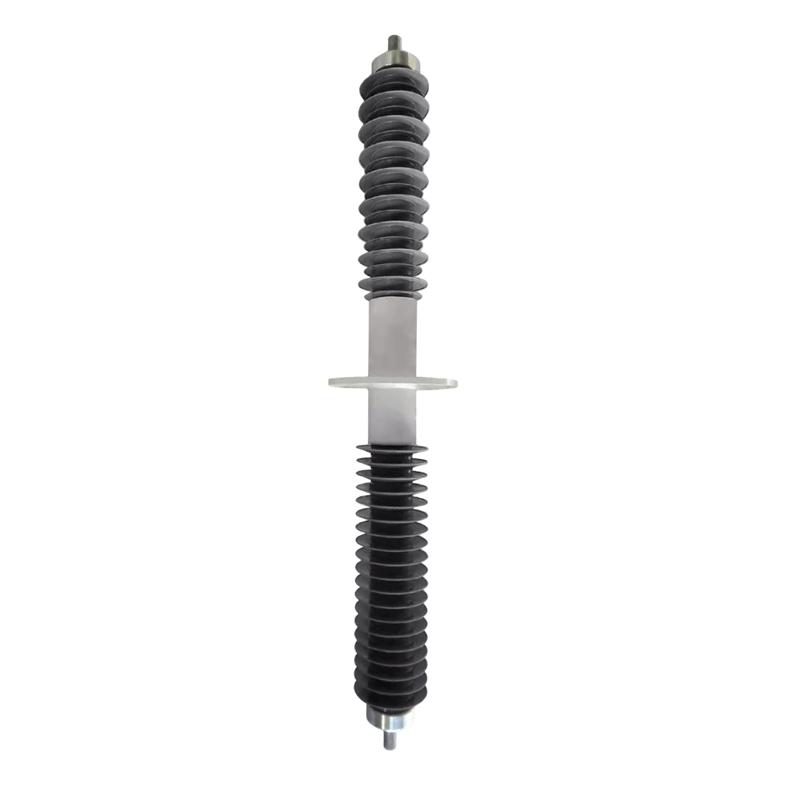
Modern substations face strict spatial constraints. They also require stringent fire-safety compliance. Routing high voltage through grounded barriers poses a serious engineering challenge. Substation walls and metal enclosures demand reliable electrical pathways. Legacy systems often rely on oil-impregnated paper (OIP) or SF6 gas. These legacy fluids introduce severe leakage risks. They also create complex environmental liabilities and high maintenance burdens. Engineers need a safer, solid-state structural solution.
The HV dry wall bushing provides this exact solution. It utilizes Resin Impregnated Paper (RIP) or Resin Impregnated Synthetic (RIS) technology. You can route high voltage safely without fluid leaks. This completely removes the risk of catastrophic oil fires. It also eliminates the greenhouse gas reporting required for SF6 equipment.
We evaluate dry-type bushings based on strict criteria. This guide examines technical specifications, environmental derating, layout compliance, and condition assessment. You will learn how to specify these components effectively. Proper selection ensures maximum safety and grid reliability.
Insulation Evolution: Dry-type Resin Impregnated Paper (RIP) and Synthetics (RIS) eliminate oil leakages, achieving partial discharge-free (PD-free) performance.
Layout Compliance: Integration requires strict adherence to phase rotation mirroring and standard ANSI layout positioning.
Environmental Sizing: Proper specification demands altitude and temperature derating (e.g., standard sizing applies up to 1000m and 40°C).
Health Monitoring: Lifecycle reliability hinges on baseline and routine testing of Capacitance (C) and Dissipation Factor (tanδ) via test taps.
Legacy insulation systems present hard limitations. Substation engineers deal with these drawbacks daily. Oil-Impregnated Paper (OIP) requires routine fluid level checks. It poses serious flammability risks. A single internal short can ignite the oil volume. You must also mount OIP equipment at strict vertical or near-vertical angles. Gravity dictates the oil distribution. SF6 gas-insulated options offer a compact footprint. However, they carry severe greenhouse gas liabilities. Environmental agencies mandate strict leakage reporting. Managing SF6 inventory drains operational resources.
Dry-type technology offers a massive engineering advantage. RIP and RIS cores utilize a solid-state capacitive design. Manufacturers wind layers of paper or synthetic material with conductive foils. They impregnate this matrix with epoxy resin under a vacuum. This creates a uniform electrical field distribution. You do not need any liquid dielectrics to manage voltage stress.
This solid-state core enables omnidirectional mounting. You can mount them vertically, horizontally, or at steep operational angles. Substation spaces are often highly restricted. Compact urban grids demand creative layout geometries. This mounting flexibility proves critical. Furthermore, the internal core remains completely maintenance-free. You eliminate oil sampling, dissolved gas analysis, and fluid top-offs entirely.
You must match external physical characteristics to the specific environment. Manufacturers provide two primary housing materials. Polymer housings utilize hydrophobic silicone rubber. They shed water instantly. They are extremely lightweight and highly shatter-resistant. In contrast, consider the traditional porcelain transformer bushing. Porcelain offers incredible mechanical compression strength. It resists scratching and chemical degradation. However, porcelain is much heavier. It is also brittle and prone to catastrophic shattering during seismic events.
Insulation coordination prevents substation flashovers. You must evaluate creepage distances carefully. Creepage is the shortest path along the insulator surface between two conductive parts. High pollution areas require extended creepage paths. Typical designs require 2.5cm to 3.1cm per kV. These extended distances resist heavy industrial or coastal pollution. You must coordinate this creepage with adjacent line components. A disc suspension insulator often sits nearby on the transmission side. You will also see glass insulator arrays on the busbars. Proper spacing stops dangerous electrical arcs across the entire system.
Environmental derating is a non-negotiable engineering reality. Substation equipment operates under specific baseline conditions. When conditions exceed these baselines, you must adjust the performance expectations.
Standard operating temperatures span -40°C to 40°C. Ambient temperatures often exceed 40°C in desert climates. You must derate the current capacity accordingly. High heat reduces the thermal dissipation capacity of the central conductor. A common engineering rule dictates a 1.8% current derating per °C over the 40°C threshold.
Altitude also aggressively dictates performance limits. Standard designs cap at 1,000 meters above sea level. Air becomes physically thinner at higher elevations. Thinner air holds significantly lower dielectric strength. It ionizes much faster under high voltage stress. You need custom "plateau-type" geometries for higher altitudes. Installations up to 3,000 meters require extended dry arcing distances to prevent sudden dielectric breakdown.
Chart: Environmental Derating Factors | |||
Environmental Factor | Standard Operating Range | Extreme Condition | Required Engineering Adjustment |
|---|---|---|---|
Ambient Temperature | -40°C to +40°C | > 40°C | Apply ~1.8% current derating per °C above limit. |
Installation Altitude | Up to 1,000 meters | 1,000m to 3,000m | Specify plateau-type design; increase creepage/arcing distance. |
Pollution Severity | Light to Medium | Heavy/Coastal (Class III/IV) | Increase creepage distance to 3.1cm/kV; prefer silicone rubber. |
Integration requires precise physical footprints. Safety standard compliance guides every architectural step. You cannot guess component positioning. You must follow standard layout configurations rigorously. An ANSI transformer bushing layout dictates strict positional sequencing. Engineers locate the nameplate to identify the front face. We label this front face as Side 1. You then move clockwise around the equipment. You mark Side 2 on the left, Side 3 on the back, and Side 4 on the right. This standardized mapping ensures safe operator access.
Phase rotation mirroring is an absolute engineering necessity. You must sequence phases correctly across the equipment boundary. Low voltage designations typically follow an X0, X1, X2, X3 pattern. You must align these terminals perfectly with the connecting switchgear or circuit breakers. The physical layout must create a "mirror image" alignment. Improper phase rotation causes immediate grid synchronization failure.
Terminal enclosures protect exposed high-voltage components. Personnel safety relies on these physical barriers. You must evaluate terminal protections carefully. We generally categorize enclosures into three main types.
Flange Enclosures: Flanges provide rigid transition points. They bolt directly to the grounded tank or wall. You use them for direct, rigid bus connections.
Throat Enclosures: A throat is essentially an extended flange. It provides a sealed duct between two pieces of equipment. Throat enclosures work perfectly for low-voltage hard bus connections transitioning into switchgear.
Air Terminal Chambers (ATC): An ATC offers a significantly larger internal volume. You need an ATC for flexible cable connections. Heavy high-voltage cables demand wide bending radii. The ATC accommodates this physical sweeping curve safely.
Pre-energization testing confirms factory health before grid connection. You must capture baseline metrics immediately upon arrival. We call these the "golden metrics" of electrical health. They provide the ultimate benchmark for the unit's entire service life.
The core metrics are Capacitance (C) and Dielectric Loss, also known as Dissipation Factor (tanδ). You measure these values through a dedicated test tap located near the mounting flange. Routine testing tracks these numbers against the factory baseline. An increasing tanδ indicates serious internal trouble. It signals moisture ingress or localized insulation breakdown. If the capacitive layers short together, the measured capacitance will increase. Routine tracking prevents catastrophic, unexpected failures.
Mechanical installation risks require strict mitigation. Electrical failures often stem from poor physical handling. You must focus on gasket seating and fastener torqueing. Improper gasket seating causes immediate mechanical failure. It invites moisture straight into the flange assembly.
Inspect Mating Surfaces: Clean all metal flanges thoroughly. Remove any dirt, old adhesive, or shipping grease.
Seat the Neoprene Plates: Place the oil-resistant neoprene plates precisely. Do not stretch or pinch the rubber.
Apply Torque Sequentially: Tighten the spring grip nuts using a star pattern. This ensures even compression across the flange.
Use Calibrated Tools: You must use calibrated torque wrenches. Excessive torque fractures the flange or cracks the porcelain. Inadequate torque compromises the hermetic seal.
Procurement teams must evaluate initial capital expenditure carefully. Dry-type units carry a higher initial CAPEX than conventional OIP variants. Upfront costs directly reflect the advanced manufacturing processes involved. You are paying for precision vacuum resin impregnation and solid-state curing. This precise manufacturing guarantees a void-free insulating core.
Buyers need a structured shortlisting logic. You cannot select these components based on price alone. Grid reliability depends on stringent manufacturing standards. Use a strict supplier evaluation checklist before issuing a purchase order.
First, verify IEC 60137 or IEEE standard compliance. These standards dictate acceptable thermal and dynamic limits. Second, require clear factory acceptance test (FAT) documentation. The supplier must prove partial discharge-free (PD-free) performance at maximum rated voltage. Third, assess specialized customization capabilities. Standard dimensions rarely fit complex retrofit projects. You might need non-standard wall thicknesses or extended ground shields.
Consider the central conductor rod material carefully. Copper offers excellent conductivity and handles high thermal loads. Aluminum provides a lighter, cost-effective alternative for lower current ratings. Finally, verify High-Voltage Direct Current (HVDC) compatibility if applicable. Specialized transmission setups require advanced field grading. Ensure the manufacturer supports extreme voltage stresses from ±50kV up to ±800kV without breaking down.
Selecting a dry-type component requires balancing electrical stress management with strict physical constraints. You must navigate insulation materials, environmental variables, and standard layouts. Solid-state technology eliminates legacy fluid risks entirely. Polymer housings offer distinct safety advantages over brittle ceramics. Proper testing ensures decades of reliable performance.
Engineers should finalize their phase alignments early in the design phase. You must calculate creepage requirements and environmental derating accurately. Engage manufacturers only after solidifying these baseline parameters. Establish strict FAT requirements to guarantee PD-free performance before installation.
A: Yes, specially graded RIP/RIS bushings are designed to handle extreme DC voltage stresses. They support applications up to ±800kV. The solid-state core prevents severe DC field distortion.
A: Electrical power remains constant across the transformer. Therefore, a lower voltage equates to a significantly higher current. The central conductor rod must be physically larger in diameter to manage the thermal load of the higher amperage safely.
A: While considered "maintenance-free" regarding fluid levels, testing remains critical. You should conduct visual inspections for housing cracks annually. Diagnostic electrical tests (C & tanδ) should align with the primary equipment's maintenance schedule, typically every 3–5 years.
